Backyard Railway.
Not suitable for commercial use, it’s an adult toy. I started working on it as a hobby in 1971 and had made most of it by 1991. I am now 82 and too old and feeble to play with it; perhaps someone would like to take it off my hands.
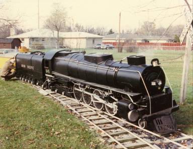
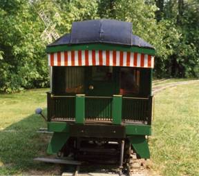
I attempted to make a railway as like the real thing as I
could, ¼ scale and running on 15 inch gauge track. It comprises a model of a
steam locomotive based on a Union Pacific
There is a dummy electric generator on top of the boiler which exhausts steam constantly; the steam pressure activates a switch which lights up the headlight.
One electric motor drives the rear locomotive truck; a second drives a pair of wheels in the tender. The motors are converted automobile generators- pre dating alternators-which make excellent shunt wound motors of about 1hp. With a 16:1 reduction belt drive a fast walking speed is obtained with a lot of power. Speed control is by the locomotive throttle which switches resistors in series with the armature as well as controlling the amount of steam directed up the chimney. The reverse gear which operates like a real loco shortening the piston stroke, (changing the cut off in a real loco) which changes the sound, and adds resistors in the field of the motor increasing the speed. The electric motor driven reverse gear is also used to reverse the polarity of the field making the loco go forwards or backwards.
The sound effect electronics are hidden inside the housing in front of the loco boiler that contained a cooling radiator for the compressed air in the real loco, with doors for access.
Power is from 6 marine batteries inside the tender, 4 (48v) for the loco motors which are in series and 2 for the 24v for the power amplifiers 12v also used for electronics and a fan that blows up the chimney generating some draught for the fire and directing the smoke from the coal fire up the chimney. Another fan directs air to the fire to heat the water and provide the steam.
The loco driving wheels are independently sprung and made from marine plywood encased in aluminum filled epoxy of the type often used to make press tools. The Loco and tender front truck wheels were turned from plastic wheels used for machine shop carts. The loco rear truck and the 12 tender wheels were made from 9 inch automobile brake drums.
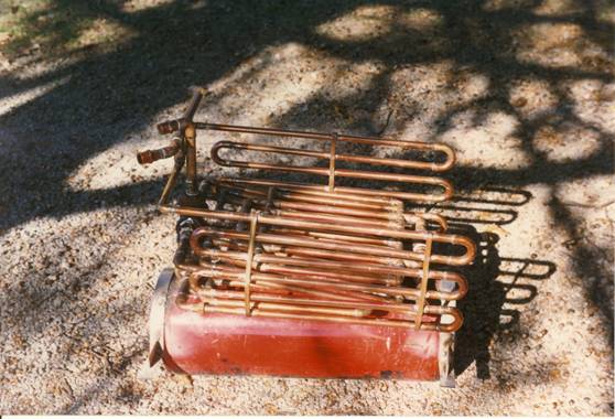 Picture of Boiler upside
down.
Picture of Boiler upside
down.
The boiler consists of a reservoir, actually an air tank with copper water pipes just above the fire set in a fire box. Two domestic water heater safety valves on the top are set to 14lbs and 15lbs/sq in. There is a filler plug on top as well, when not in use the boiler is filled with neat antifreeze to prevent rusting. There is a glass water level indicator like on a real loco. I had to leave the loco once when it was low on water, the solder on the copper pipes melted which came apart and released any pressure. It was a mess but safe, I had to rebuild the whole boiler!
Two water connections are provided to the boiler, one for adding water kept in a tank in the tender via an electric pump in the loco cab, and this water goes through serpentine copper pipes each side of the fire which keeps it hot, then through a one way valve. Another water connection on the bottom of the boiler is for emptying the boiler, best done while there is a small amount of pressure in the boiler 2-3 lbs. A threaded connection welded to the top of the boiler goes to the two safety valves and to the separate valves along the back of the boiler casing top, feeding steam to the throttle, dummy generator, air pump etc. There is also a valve to feed steam back to the coaches to simulate steam heat.
The locomotive boiler casing is made of galvanized steel, the chassis from marine plywood and aluminum and some other parts from yellow pine.
The tender:
Holds the batteries and a tank of water in addition to the coal for the fire available from a door next to the footplate of the loco as in the real loco. There are connections to the loco for water and electric power.
Part of the front of the tender can be arranged to provide a seat if one desires to control the loco from there.
The front and rear tender wheels are fixed laterally but the others are free to move sideways on curves. The center wheels are driven with an electric motor with the same reduction gear as the loco motor. The front and rear tender wheels have brake shoes operated by an air cylinder the air controlled from the loco cab via a solenoid. There is an air storage tank inside the tender.
The center of one side of the tender is removable for access to the batteries, the motor, air tank etc. There is a battery charger that charges the two batteries used for the electronics. I have a homemade automatic charger to charge the 4 batteries used for motive power, separate from the tender.
The Diesel.
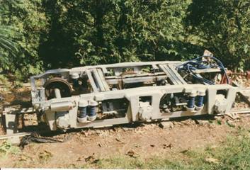
Diesel Truck.
Pushing the heavy tender full of batteries out of the shed to couple it up to the loco made me think about making a diesel shunter to do the job, which ended up in me making a passenger diesel, an Alco PA2 for reasons explained later.
The diesel has fabricated trucks looking very like the full size trucks. Each truck has an electric motor and reduction gear like the ones in the steam loco, driving the center pair of wheels which have some lateral movement.
8 HP Tecumseh and control panel for the electric motors.
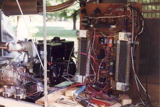
Power is from the 8hp Tecumseh lawn tractor engine in the photo driving a 400 amp 28v aircraft generator and a 14v automobile alternator to charge the battery used to start the 8hp engine, the low voltage for the electronics and the relays. For starting the generator is switched to operate as a motor with a start/run switch in the cab. I fitted the Tecumseh with a home made automatic choke.
The Tecumseh and the two generators are mounted on springs to absorb the vibration from the single cylinder engine. The truck motors are wired in parallel controlled by a control unit in the cab in which one can sit. The control panel seen in the photo is connected to the control unit in the cab and contains the switching relays, -two 1Kw resistor banks can be seen, and the unit controls the switching of resistors in series with the motor armatures and the motor field windings. As the current is fairly high the actual switching is done with automobile starter relays. When the controller is operated to make the diesel run the throttle on the engine is also automatically operated by an electric motor, full or half power by a switch in the cab. Forward and reverse are controlled by a relay switching the motor field windings. A surplus 28v air compressor from a military aircraft supplies air for the brakes, each truck has brakes on front and rear wheels; air is also used for the air horn on top of the cab. An air line at the rear of the diesel feeds air to the coaches for braking, although control of the braking is electric via air solenoid valves in the coaches, controlled from the cab.
The exhaust from
the engine goes via a 50 gallon oil drum as a resonator and a muffler to the
exhaust outlet in the center cab top. It doesn’t sound like a 16 cylinder
diesel but it also doesn’t sound like a lawn tractor. l.
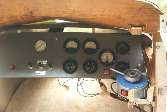
Cab instruments showing air pressure 28v and14v supplies, field current forward or reverse, current in the truck motors, start button (red LH)
Start/run SW, Air compressor on/off SW, headlamp SW, full/half power red button. Controller on right with forward or reverse rocker SW and the brakes on/off SW which can’t be seen in photo.
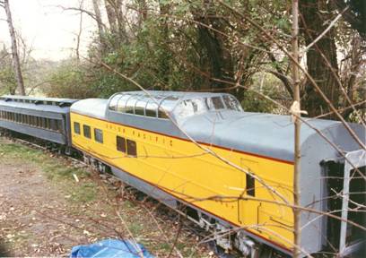
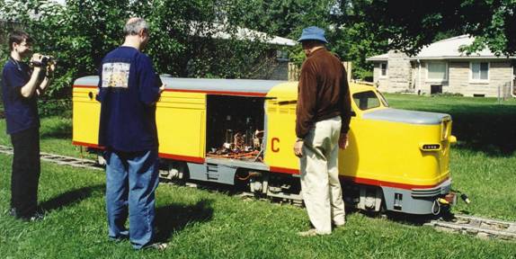
Two coaches; a Dome Diner and a 1920’s
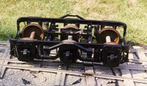
Six wheel truck for
Pullman truck has brakes which don’t work very well, need some more work. Part of the Pullman car side is removable and part of the roof to allow people to sit in the coach.
A pipe runs the length of each coach with a coupling at each end through which steam from the loco can be sent, a vent near the center allows some steam to escape simulating the steam heat, looks good on a cold day.
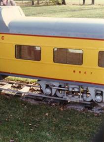 Photo of Diner Truck.
The other coach is a Dome Diner. A door in the side allows children to get inside. Adults can also sit in the diner part which has more headroom. The trucks are fabricated to be very like the full size ones, are sprung and have some lateral movement. Both have brakes and air cylinders, the air being controlled by electric valves operated from the diesel cab. An air reservoir tank is mounted in the coach bottom with a gauge. When pulled by the diesel the air cylinder is filled by the compressor in the diesel.
Couplings: The coupling between the coaches are scale castings I bought from another 15 gauge railroad but they only had two, non automatic. For the rest I fabricated pairs of automatic couplings that work fairly well.
On the front of the smoke box is a bell which has a loudspeaker inside it, the bell sound electronics are in the loco cab. A scale size bell is too small and doesn’t sound like a locomotive bell hence the electronics.
I made a remote control for the steam loco using the remote
control circuitry from an old TV. It controls throttle up and down (an electric
motor moves the throttle lever), Forward and reverse,
The receiver is inside the tender with the control relays.
For the future I had started to modify the steam loco so that instead of using batteries I would run the steam loco from the power in the diesel. The six batteries are extremely heavy. The diesel has enough power to move the un-powered steam loco including batteries so it shouldn’t be a problem.
The motors in the steam loco are in series, but it’s quite possible that with 28V from the diesel, the steam engine would be fast enough when pushed by the diesel. The 28V could also power the amplifier and the 14V from the diesel the electronics, and the fans.
The track is actually 7.5 inch gauge track set 15in apart but adequate for the weight of this train and easier to work with.